Well. Buttons yes, hopefully not so much of the 'doom' part!
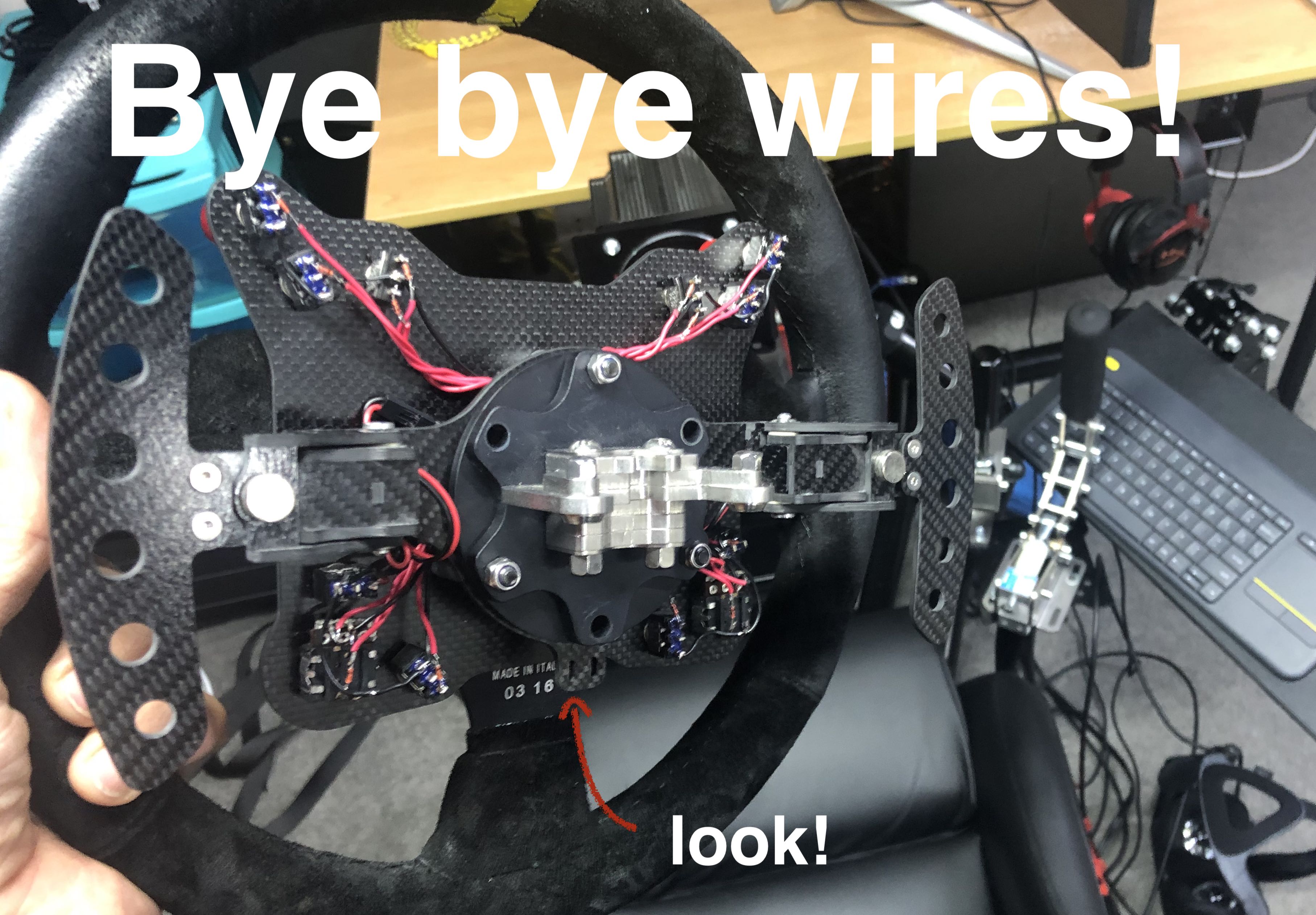
I had a wired wheel with 16 buttons, 2 shifters and 2 rotary encoders. I'd originally built it for road racing (iRacing), and that worked fine for a couple of years. As I began to get into dirt, the cord started getting in the way. Grr. Cord be gone!
I looked around for existing stuff, and found a project that used 2 Arduinos in I think UART mode. The idea was you preconfigured them to talk to each other, and exposed one of them as a Joystick device on the PC. I'd list the project here but I can't find it again.
After hunting a bit I found the adafruit feather. Docs and such for this board are here: https://learn.adafruit.com/bluefruit-nrf52-feather-learning-guide/introduction. This looked promising as it was an Arduino, and BLE, with Lipo charger, in a single unit.
What this project does is make the wheel appear as a Joystick device directly over BLE.
- 1 x Feather BLE (I used the no-pins one)
- 18 x Signal Diodes (one per button)
- A whole bunch of wire
- The ability to solder :)
- Soldering iron!
- Maybe a separate lipo charger (for convenience)
What's the reason for the diodes I hear you ask? Answer: so we can be efficient. While it is possible to have 20 odd inputs for the 16 buttons & 2 encoders, you won't have anything left for 'other stuff'. Ask me how I know.
If you wanted to (as I did) have an LED for battery status: you're out of luck. Enter 'matrix keyboards'. While the wiring is more complex, the result is you can use a 4x4 matrix to get 16 inputs, leaving loads of pins available for other things. Like lights! Lights are shiny. We like lights.
Here's the (pinout for the Feather](https://learn.adafruit.com/bluefruit-nrf52-feather-learning-guide/device-pinout).
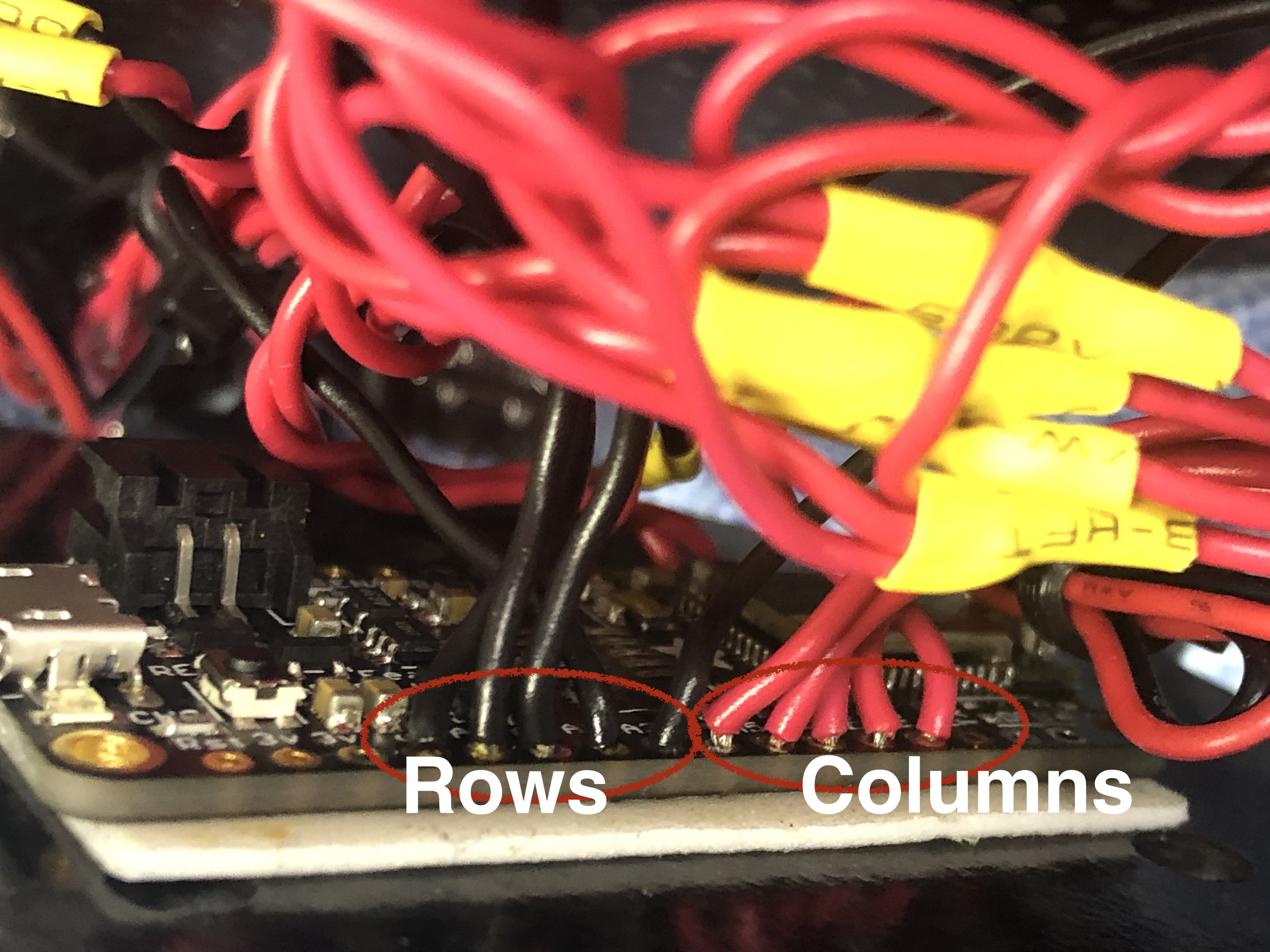
- I used A0-A3 for my 'rows' and A4-A7 for the 'columns'.
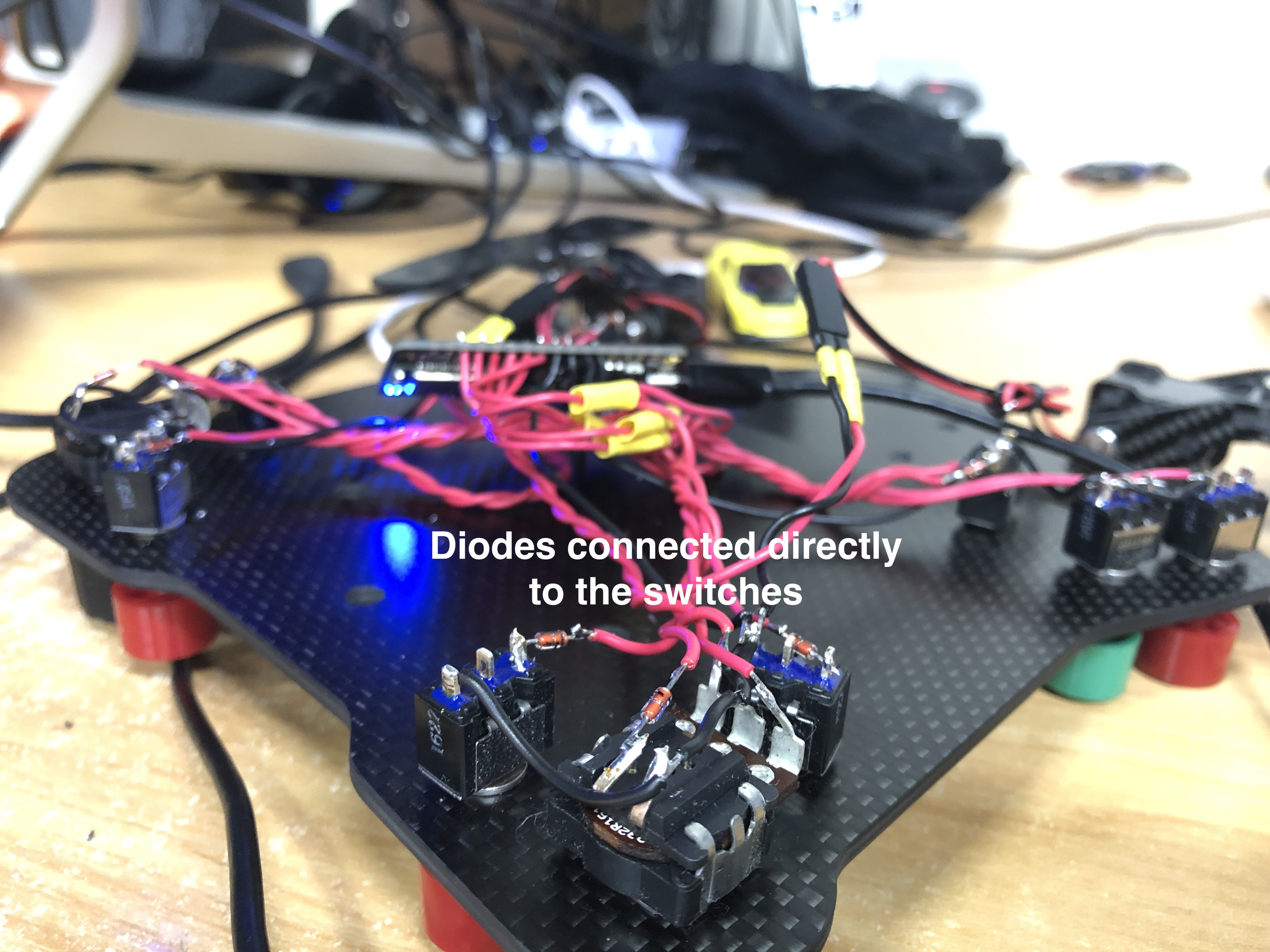
Re matrix wiring, I used the diagram from Bald Engineer | Matrix Keyboard as a reference. I then used the Keypad arduino library to read the matrix.
Note the use of diodes at each switch.
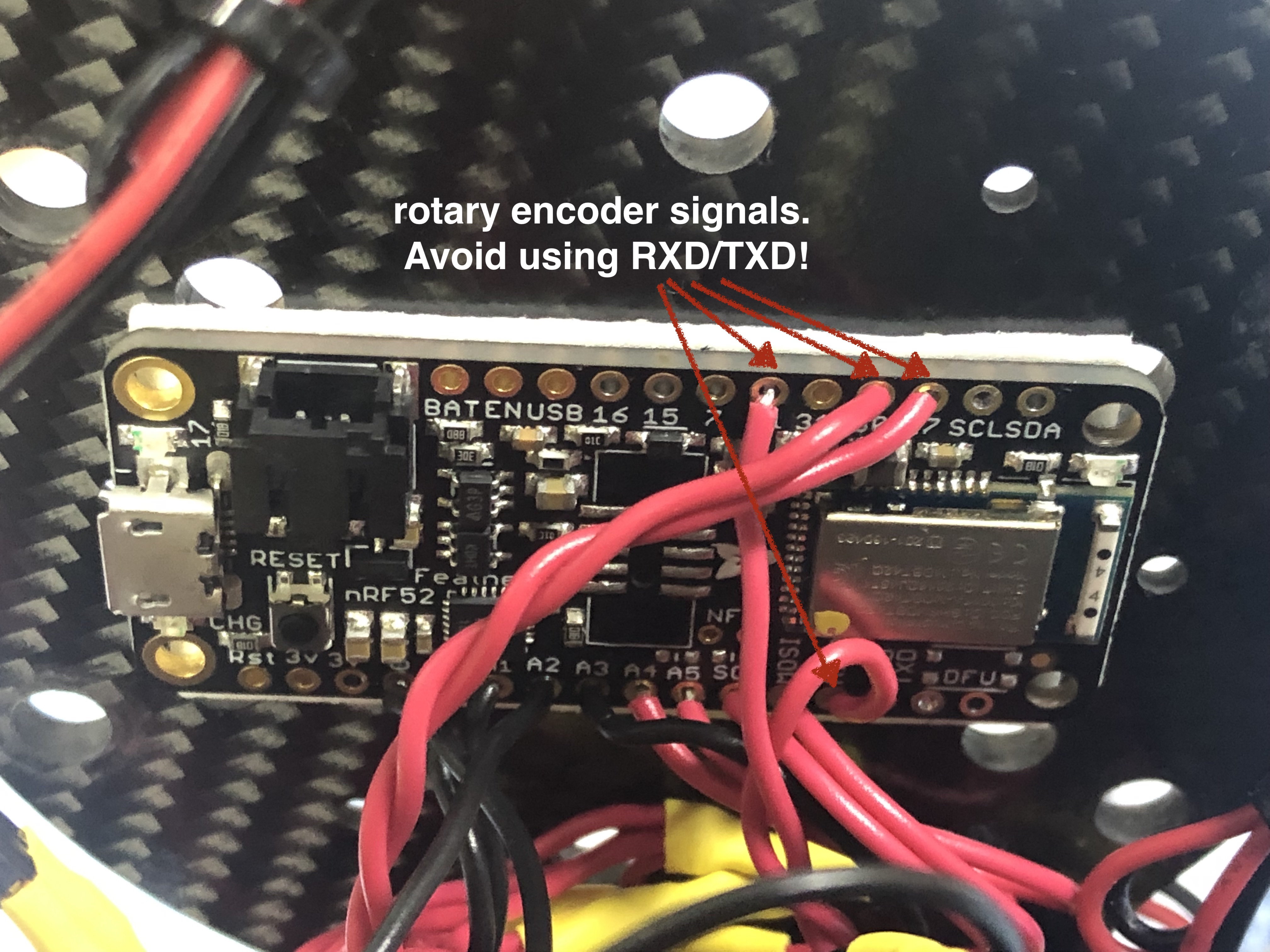
- Encoder 1 uses pins 14,11
- Encoder 2 uses pins 30,27
The code here is specifically for my wheel. By that I mean the number of buttons I have, and the two encoders. It's easy enough to change tho ... after a bit of explanation and learning on your part :-)
Here's what's important to know:
vars.h contains most of the configuration. Go there first.
- "pinouts" for your ROWS/COLS of the matrix are in rowPins and colPins respectively.
- "button numbers" start at 0. All push buttons in the matrix are assumed to come before anything else. Rotary encoder outputs should begin at NUMBER_OF_BUTTONS (button numbers are zero relative).
- encoderConfiguration:
- Spells out the pins used for rotary encoders, and their respective button numbers.
- EncoderConfig(14, 11, 16, 17) means:
- Use pins 14, 11 for encoder input.
- Use button 16 as left, button 17 as right. (bits 15 and 16 in the HID output). This works for the first encoder because my buttons take numbers 0->15. The 2nd encoder uses buttons 18 & 19, and so on (if you had more encoders).
- If you change the number of encoders you have to change this definition.
- It seems HID inputs must be a multiple of 8 bits. Things didn't work for me otherwise. I'm no HID expert, so I just made everything a multiple of 8 and got on with it. If you're going to change the number of buttons, this is something to keep in mind. The code already more or less takes care of this for you.
- Rotary Encoders are manually configured to appear as buttons. So if you change the number of buttons, you might need to change the encoder button numbers as well.
- Don't hook a rotary encoder output to RXD/TXD (pins 8 & 6) of the feather. Depending on the encoder position, it'll stop you being able to upload new sketches to the unit.
- 31 is for reading lipo voltage. Don't use it for an input.
- Unsure if this matters for inputs, but the docs say that SCL/SDA don't have pull-up resistors. They seemed to work, but when I implemented the matrix input, I no longer needed them and avoided them.
- Maybe avoid pin 20 (DFU). If it's tied LOW it'll reset/wipe the device. Basically, go read the pinouts doc for the feather. There's lots of useful info there about pins to watch out for.
- Change NUMBER_OF_BUTTONS in vars.h
- Change ROWS/COLS to be whatever works for your wiring.
- keys[ROWS * COLS] to have consecutive integers, starting at 0.
- Set MONITOR_BATTERY to true.
- VBATPIN should be 31 (assuming a feather BLE unit)
- If your LED is too bright, use MONITOR_LED_INTENSITY to reduce.
- Assumes use of a simple RGB LED (not a pixel device or other single data line driven thing)
I had originally intended to have TWO of the Arduino units - the 2nd acting as a charger. In the end I decided to get a simple USB 1s Lipo charger. They are cheap (couple of bucks). Something like this
You could of course also make the USB port of the Feather accessible, and plug a cord directly into it when not in use.
There's a very important #define in vars.h. The one that reads:
#define PRODUCTION 1
If this is defined, there'll be NO DEBUG sent to Serial. Comment this out if you're debugging/changing stuff. You'll get a sensible summary and also notifications when buttons are pressed/released.
set NUMBER_OF_ENDCODERS to 0 in vars.h
#define NUMBER_OF_ENCODERS 0
Then change the definition in buttonplate.h to read:
EncoderConfig encoderConfiguration[NUMBER_OF_ENCODERS];
basically just remove the assignment.
Only later, as I was writing this, did I discover the blue martin. No idea why I didn't come across that first. Would I have used it? Doubt it. I don't think it'll fit nicely behind the wheel (although I couldn't spot dimensions to verify). It'd be nice if there was a smaller version of this board tho. Might use it for a separate button box if I ever do one of those... then again, I've got another Feather, so ...


